Breadboarding the VCA
I built the VCA part of the circuit on a breadboard trying to get the layout close to what I’ll solder on the protoboard.
The initial output was way too amplified and then I remembered that I had replaced the 1.8k resistor in my design with an 18k resistor to get the simulation working. I swapped it back and it fixed the issue (!?). The most obvious conclusion is that the spice model is wrong!? But that seems pretty strange to me since the model was included with TINA TI. I’d like to ask this question on a forum.
For the 2Vpp signal, I hooked it up to my new waveform generator. For the control voltage, I connected it up to my DC power supply and varied the DC voltage between 0v and 3.3V.
At 0V control, the output signal is 0Vpp. At 3.3V control, the output signal is 3.8Vpp (I was expecting 1V)
The output signal is a nice 2Vpp with essentially zero DC bias (matching what I had in the simulator):
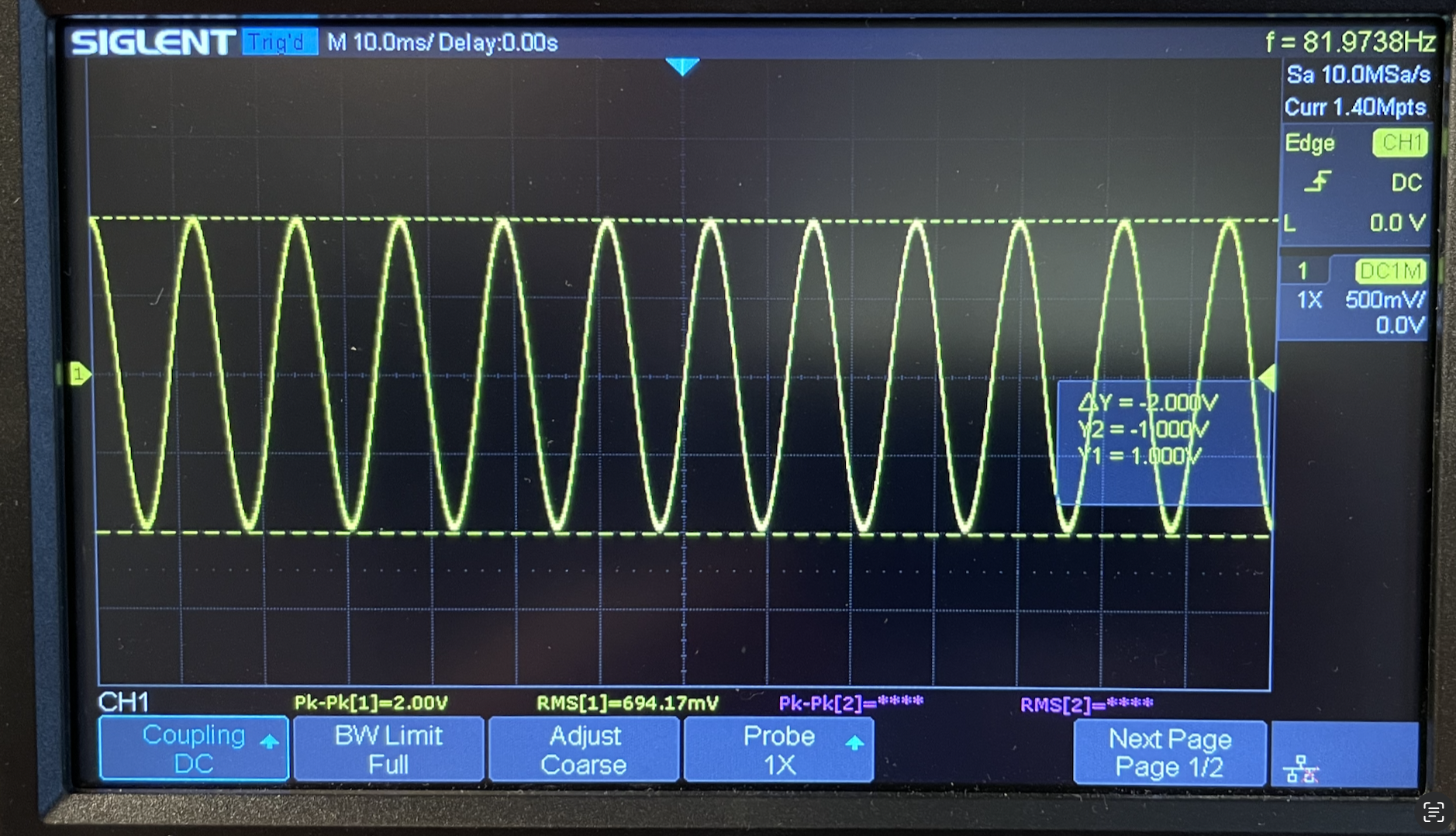
Since designing the circuit I’ve read that the output of the VCA is fairly high impedance and so needs to be buffered. The output shown in the photo above is unbuffered.
After adding an op-amp (TL072) unity gain buffer, the output signal was noticeably less stable on the scope (not shown here). Not sure why that would be! Maybe it is noise or poor connections and will go away once I solder the circuit.
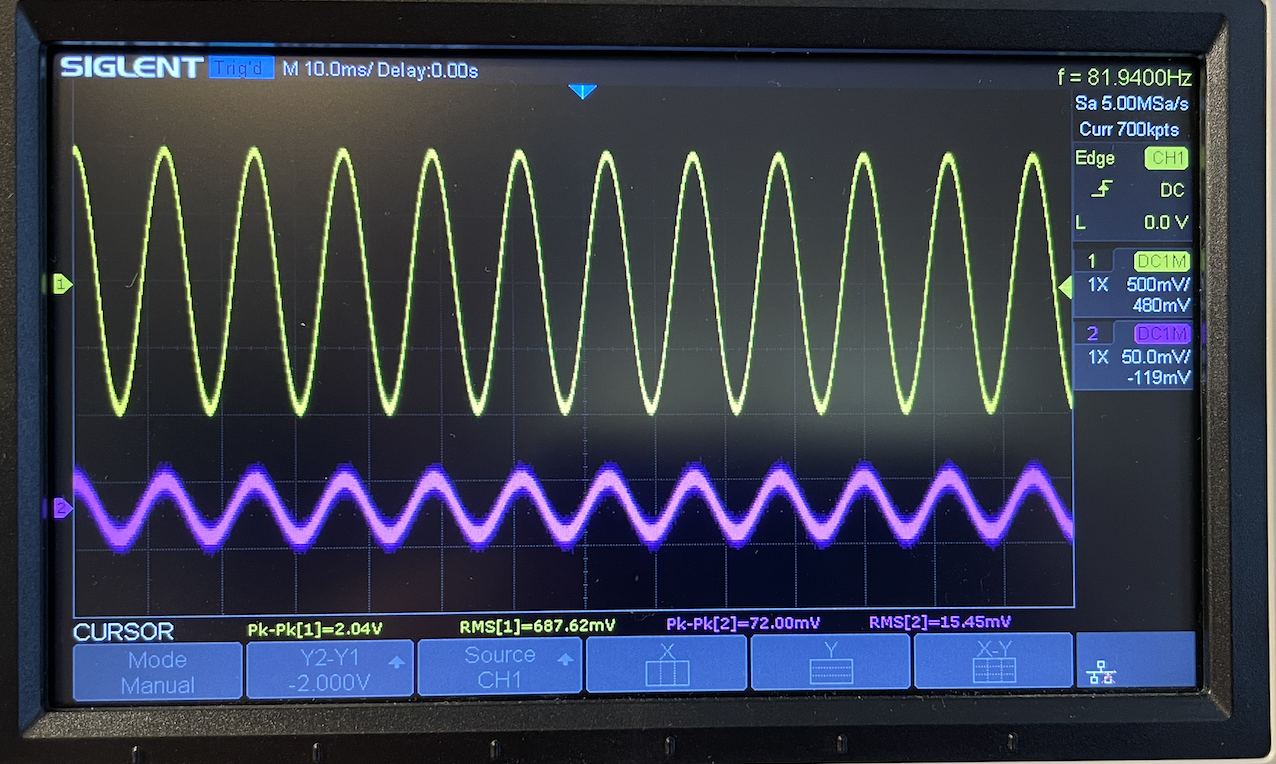
A voltage measurement at pin 3 (called VF1 in the circuit diagram) was 72Vpp, about double what I calculated and saw in the simulation. I’m guessing this is because of the amount I adjusted the trimpot to get the 2VPP output. Needs more investigation.
- ← Previous
Regarding common grounds - Next →
Soldered prototypes