Pre-Amp and Biasing for ADC in an Analog Guitar Pedal
I’m working on a guitar pedal with a friend. We’re at the prototype stage. Here are some notes re preparing the guitar signal for note detection by the ESP32’s ADC.
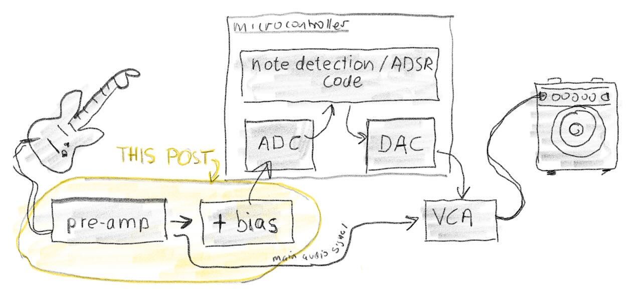
Steps
- “Power supply” with positive and negative rails and a virtual ground.
- Lower impedance and amplify signal to about 2300mv peak-to-peak.
- Bias signal approximately +1300mv to fall between 150mv and 2450mv, which is what the ADC wants.
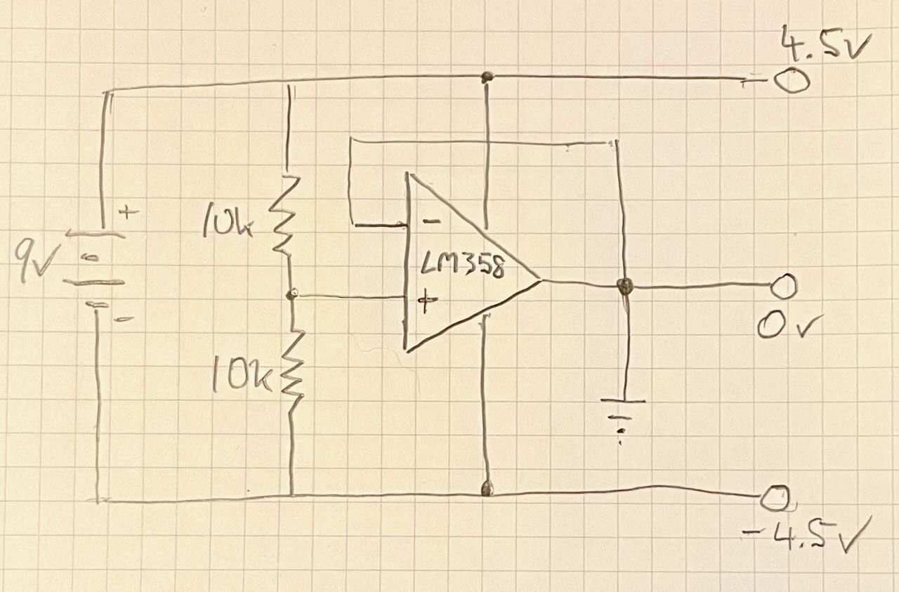
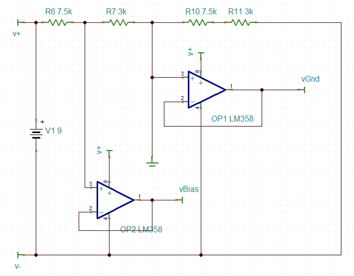
Power Supply
I decided to use a voltage divider approach to create a virtual ground from a 9 volt battery, effectively providing +/- 4.5 volts, which will be suitable to drive the analog part of the circuit.
For now I’m using an LM358 op-amp to buffer the virtual ground. If you don’t buffer the virtual ground, then the voltage division could be effected by any load that is applied.
Buffering and amplifying the signal
Passive guitar pickups provide a high impedance signal (I’m still trying to figure out how to accurately calculate the impedance, but from what I’ve read it is probably 10-20k) and varying output voltages (I’ve read 100mv to as much as 2v; my guitar outputs 400mV when plucking the low E string with force).
I need to buffer the signal (convert from high impedance to low impedance) and adjust the peak-to-peak voltage to fall within about 2 volts (5x amplification).
Here’s the circuit:
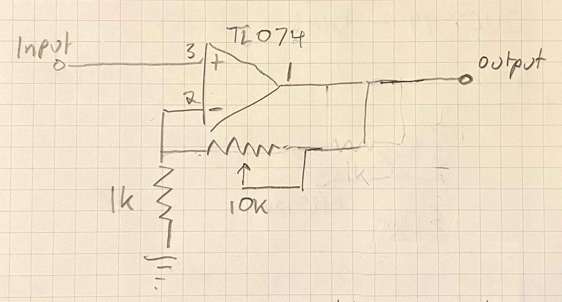
The audio signal passes through the TS074 op-amp in non-inverting amplification mode. The gain is 1x-11x depending on the potentiometer setting.
Below, the raw guitar signal (yellow) and amplified (purple):
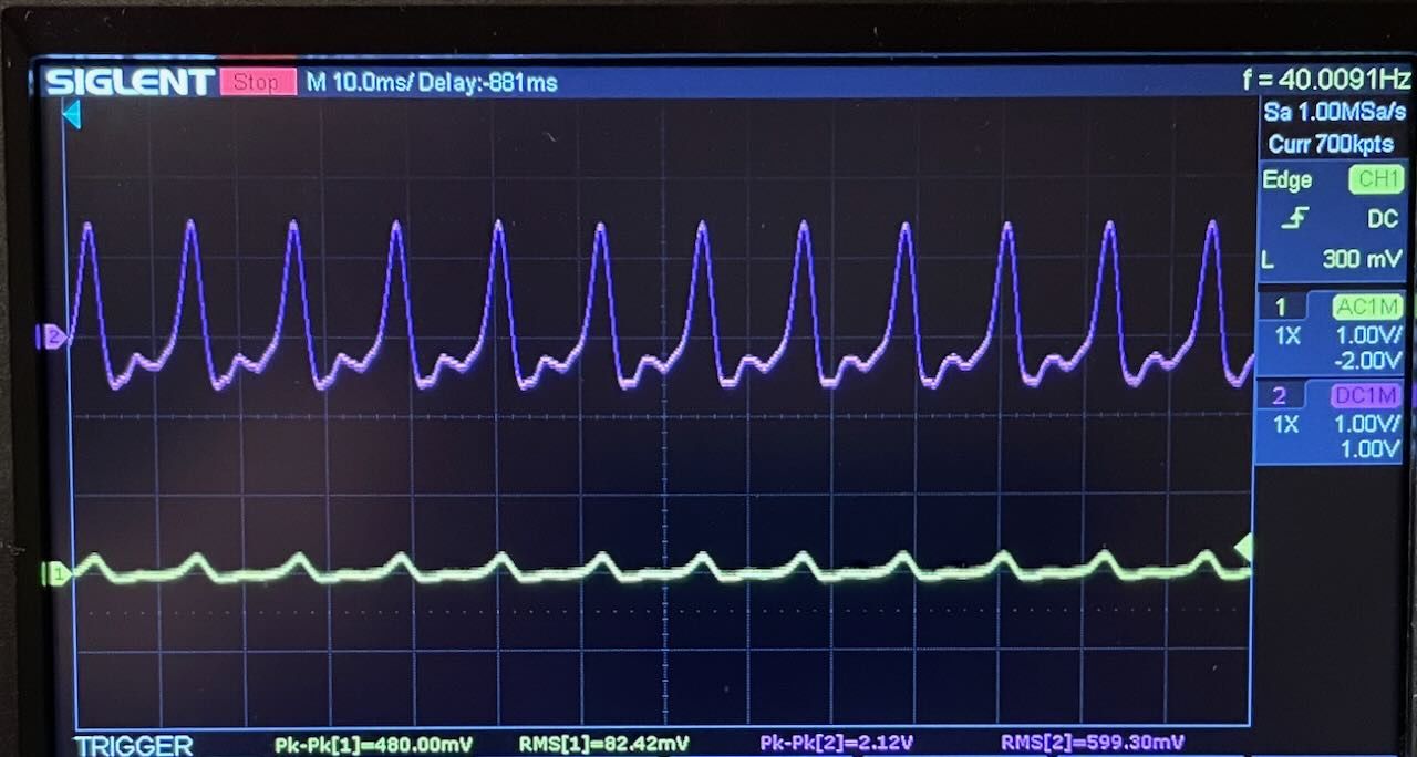
You can see on the scope: the signal from the guitar is about 480mV peak-to-peak, and the amplified signal is about 2100mV.
Biasing the signal
The ESP32 ADC cannot handle negative voltages and so the signal must be biased.
The ADC has a reference voltage of (about) 1100mv, but the input can be attenuated for readings up to about 2300mv. I plan to use the highest attenuation (DB_11) to get a range of 150 mV ~ 2450 mV.
There are a couple of different approaches for biasing the signal, but I decided to (1) use a voltage divider approach to create a bias voltage of about 1300mv, (2) buffer the bias voltage with the second op-amp in the LM358, (3) use the second op-amp in my TS074 in summation mode to add in the bias voltage to the audio signal.
The power supply circuit including the bias voltage now looks like this:
The circuit for summing the bias voltage and the pre-amp output:

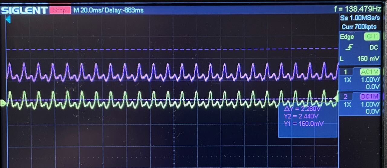
Below is the amplified audio signal (yellow) and the biased signal (purple) with 150mv and 2300mv marked in dashed lines. The signal is falling between about 900mv and 1840mv, well within the range of ADC.
TINA-TI
Here is my TSC file for TINA-TI.
- ← Previous
Guitar auto-swell pedal - Next →
Guitar pedal / ESP32 ADC trigger test