Regarding common grounds
-
I’m measuring the guitar signal via the microcontroller’s ADC relative to the virtual ground.
-
I’ve mapped 0-3.3v to 0-20ma current to control the VCA. The voltage is measured with respect to the negative rail.
I just realized that I can’t have the microcontroller tied to both the virtual ground for ADC and negative rail for VCA.
What to do?
My first impulse was to change the bias for the guitar signal going to the ADC. I want that the signal to vary around -3350mv (that is, with a maximum peak to peak voltage of 2300mV with the lowest part of the signal sitting on the negative rail). But, this requires an op-amp which supports rail-to-rail output. The TS072 does not.
My second impulse is to take the control voltage output and figure out a way to map it to 0-20ma relative to the negative rail.
A voltage to current source
Rewatching the Lanterman video, I’ve decided to use his voltage-to-current source. My version is:
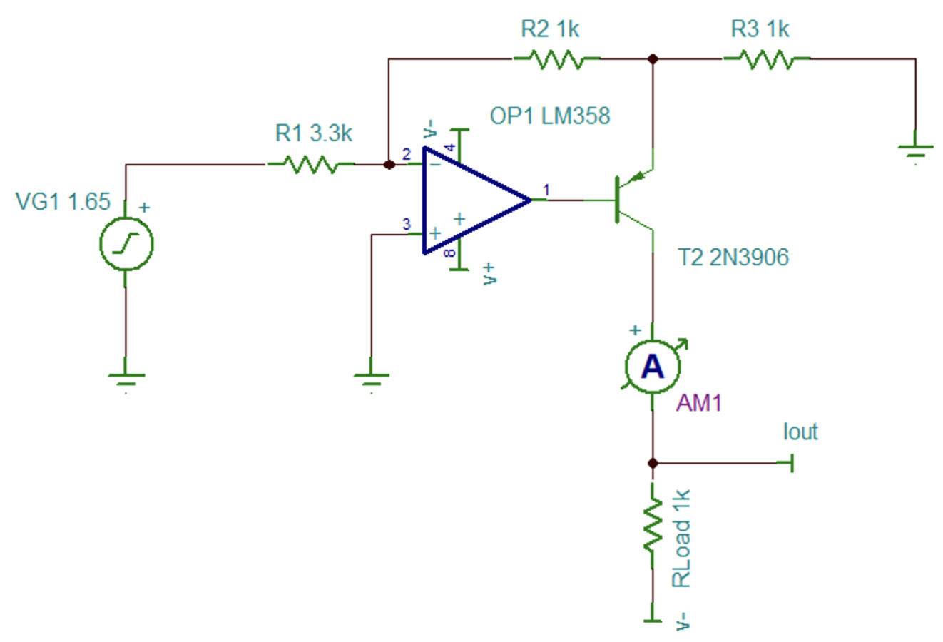
I chose the numbers for R1, R2, R3 based on starting with them all as 1k and then adjusting R1 to get a max of 2ma. R4 just represents some load. Landerman has the formula as:
Which I simplify to:
Using values for R1 = 1k, R2 = 1k, R3 = 3.3k, I get a max current of 2ma:
From the simulator:
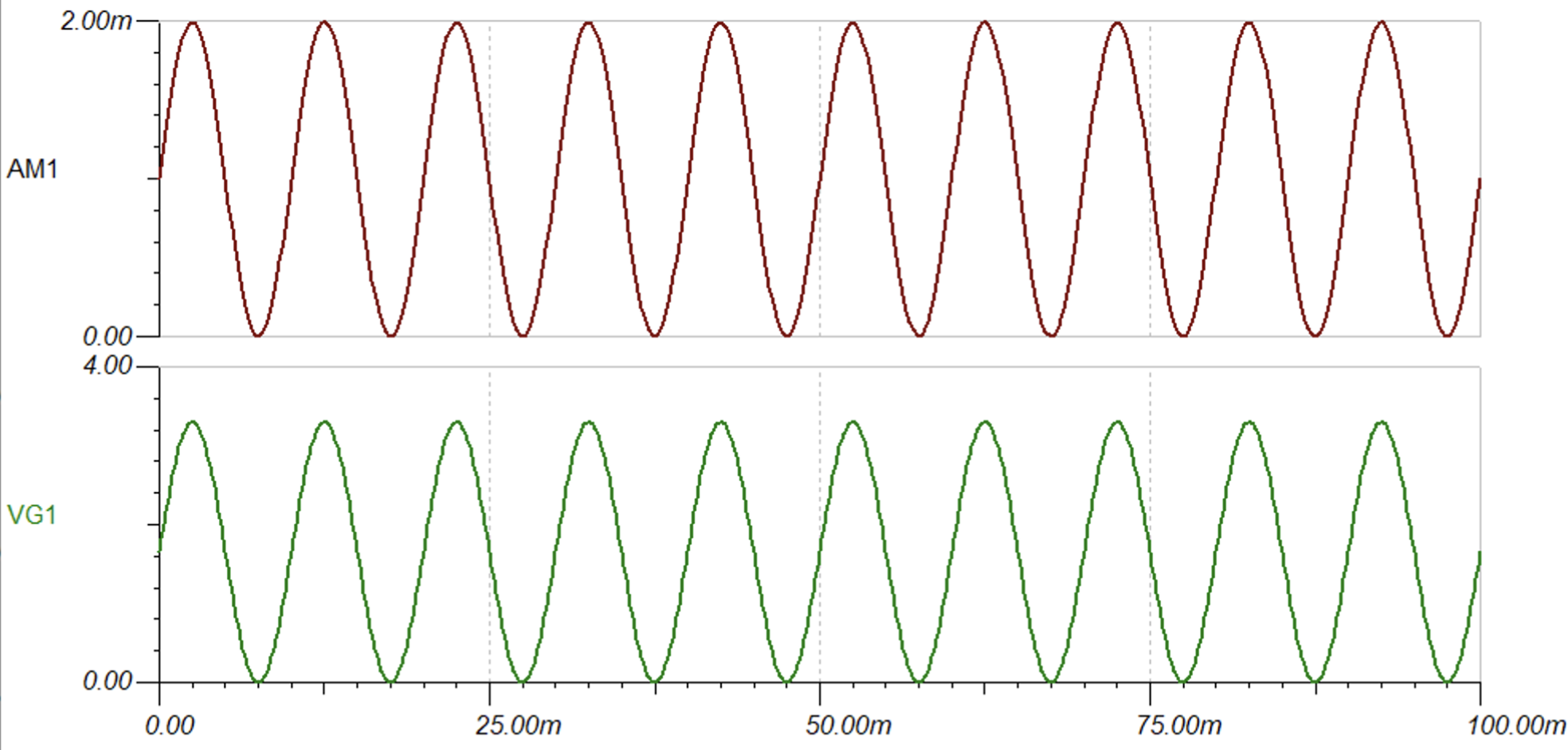
This is exactly what I want. Hopefully it works this well in practice.
- ← Previous
Designing the VCA - Next →
Breadboarding the VCA