Soldered prototypes
The multiple breadboards with wires going everywhere was becoming unwieldy. I kept knocking out a wire and then wondering why things weren’t working. So, I transferred the two circuits to a solderable breadboard. (This is my first time soldering to a protoboard :)).
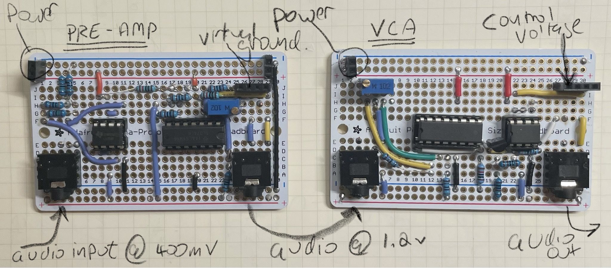
Pre-Amp Circuit
I intended to use a 1k resistor (like I had in the simulation) plus a 5k trimpot to govern the gain of the pre-amp, but accidentally used a 1k trimpot, so I have a gain of between 2-3x.
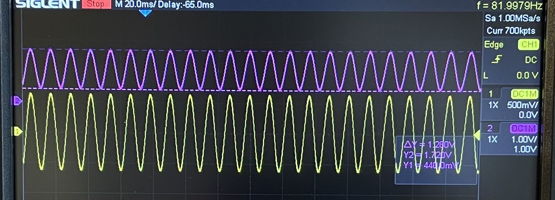
My guitar gives me about 400mVpp (at maximum volume). I simulate this with:
- Audio Input: +/- 400mVpp at 82hz
- Audio Output (shown below in yellow): 1.28Vpp
- Biased Output for the ADC (shown below in purple):
- Ranging between 440mV - 1720mV, centered at 1000mv.
- Equals 1.28Vpp
VCA Circuit
I have not connected the two circuits yet and am testing this circuit separately.
Inputs:
- Audio Input: +/- 1V sine wave at 1khz
- Control input: 0-3.3mv as sine wave at 100hz

The output is very much like what I got in the simulation.
Note: I didn’t connect the diode bias current yet (pin 2 of the LM13700). I’d like to do this at some future date when I have time to compare with vs without.
- ← Previous
Breadboarding the VCA - Next →
First end-to-end test